About GRF
Since 1997.
A rubber factory in Saudi Arabia, with its own metal shop, making rubber, metal and rubber-to-metal parts for industry in 12 countries.
 At a glanceWho we are, in numbers→
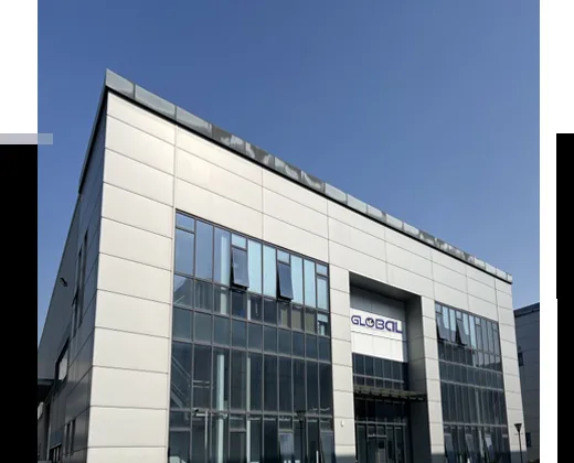 FacilitiesSaudi Arabia · UAE · USA→
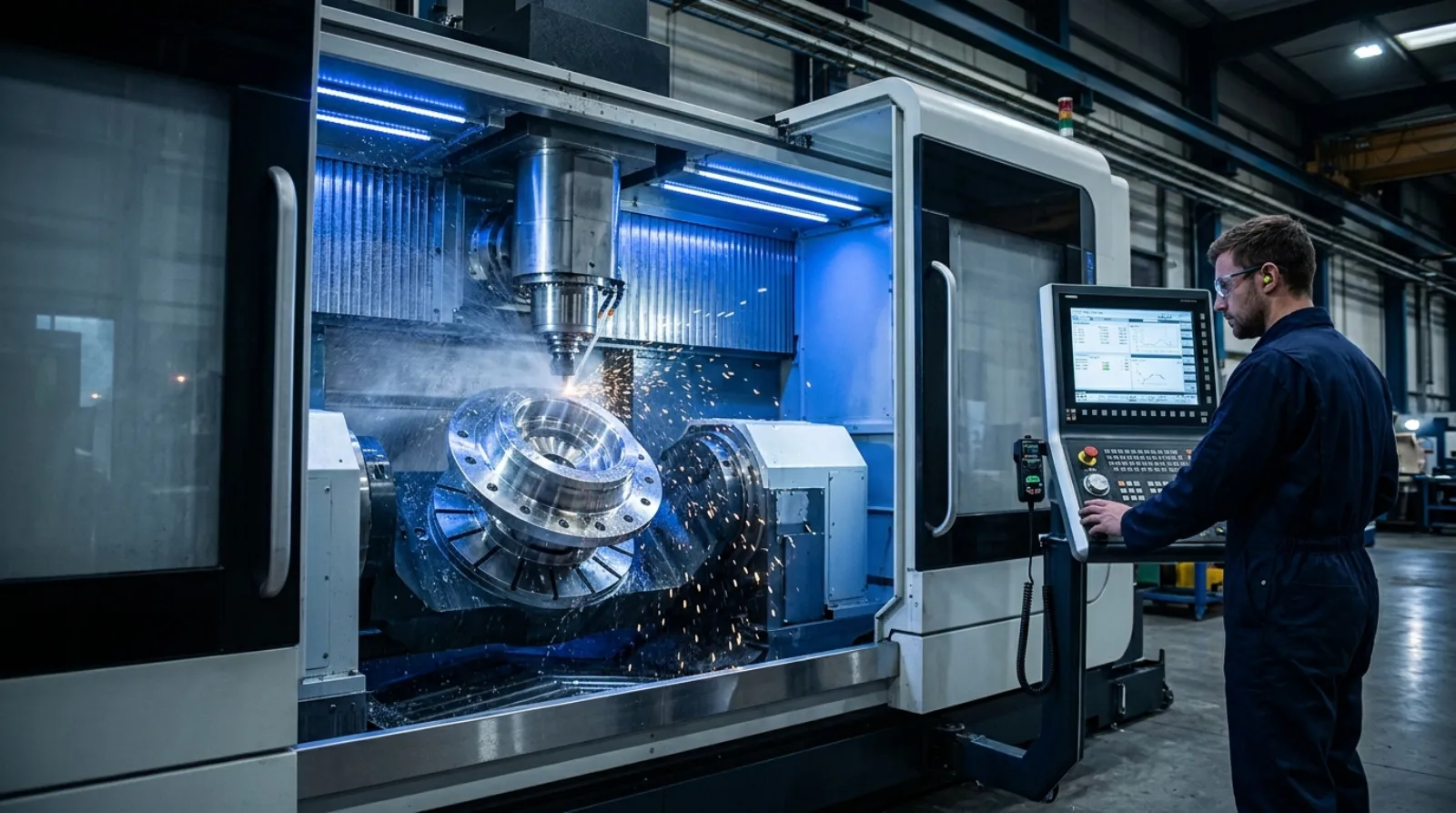 CapabilitiesFrom design to delivery→
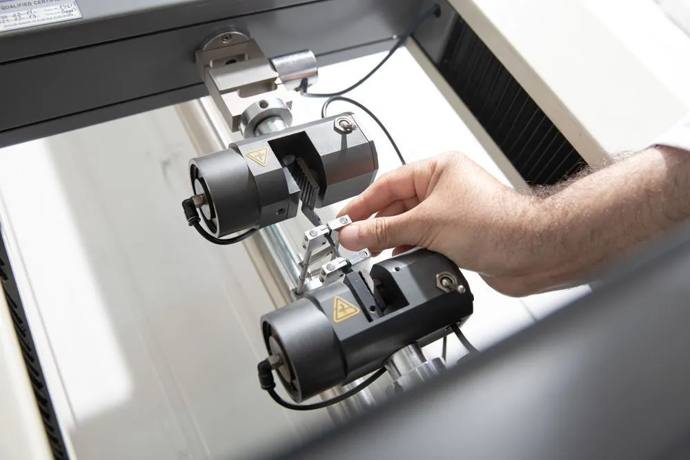 Quality & policiesISO 9001 · 14001 · 45001→
Meet our team in Jeddah, Riyadh, Dammam or Dubai.
→Contact us Mechanical test plugs8 products
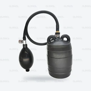 Inflatable plugs5 products
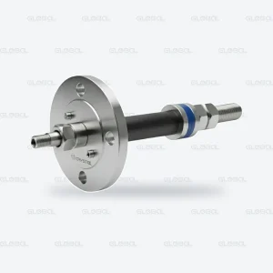 Weld test plugs3 products
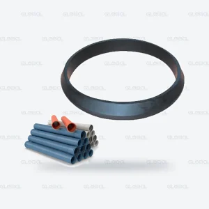 Rubber rings & seals3 products
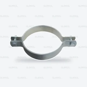
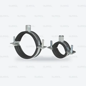 Pipe clamps & hangers2 products
 Tools & accessoriesNewMechanical test plugs7Inflatable plugs5Weld test plugs3Rubber rings & seals3Pipe clamps & hangers2Tools & accessories·CL-PLUG™Center-Lock Pipe Test Plug
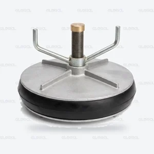 ALU-PLUG™Aluminium Pipe Test Plug
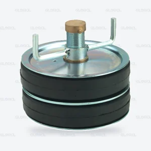 DS-PLUG™Double-Seal Pipe Test Plug
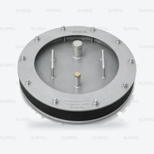 ML-PLUG™Multi-Lock Rim Fastening Test Plug
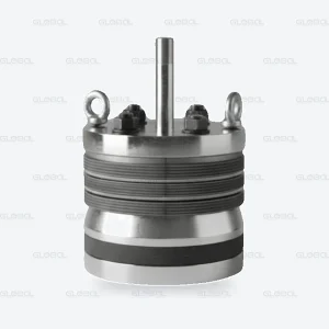 IN-MAX™High-Pressure Inner Test Plug
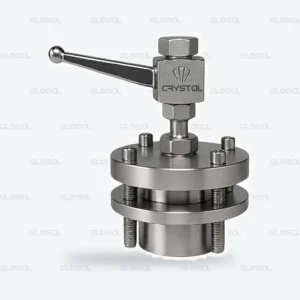 OUT-MAX™High-Pressure Outer Test Plug
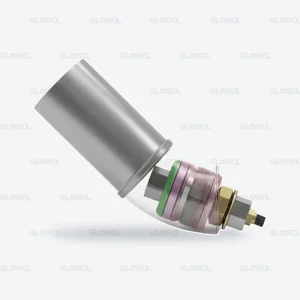 ELBOW-MAX™High-Pressure Elbow Test PlugBALL-PLUG™Balloon Pipe Test Plug
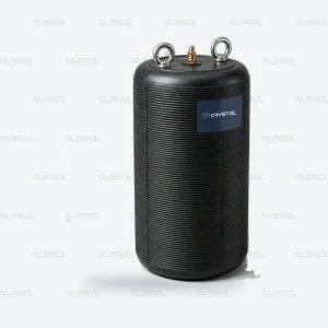 INFLA-STOP™Inflatable Pipe Stopper
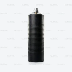 INFLA-TEST™Inflatable Pipe Test Plug with Bypass
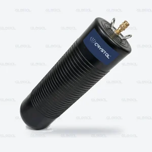 INFLA-PSTOP™High-Pressure Inflatable Pipe Stopper
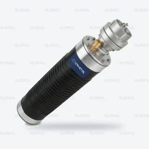 INFLA-PTEST™High-Pressure Inflatable Test Plug
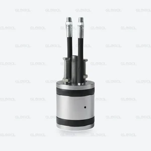 DB-WELD™Double Block Weld Tester
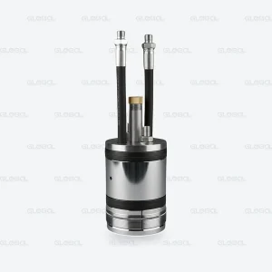 DBG-WELD™Gripper Double Block Isolation & Weld Test PlugFLANGE-WELD™Flange Weld Test & Isolation PlugTRIO-SEAL™3S Rubber Ring for PVC & UPVC Pipes
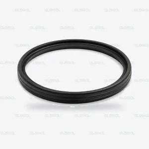 LIPRO-SEAL™Lip Seal Rubber Ring for PVC-U Pipes & Fittings
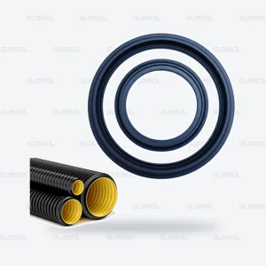 CORA-SEAL™Sealing Ring for HDPE Corrugated Pipes
New products coming soon
View all Tools & accessories →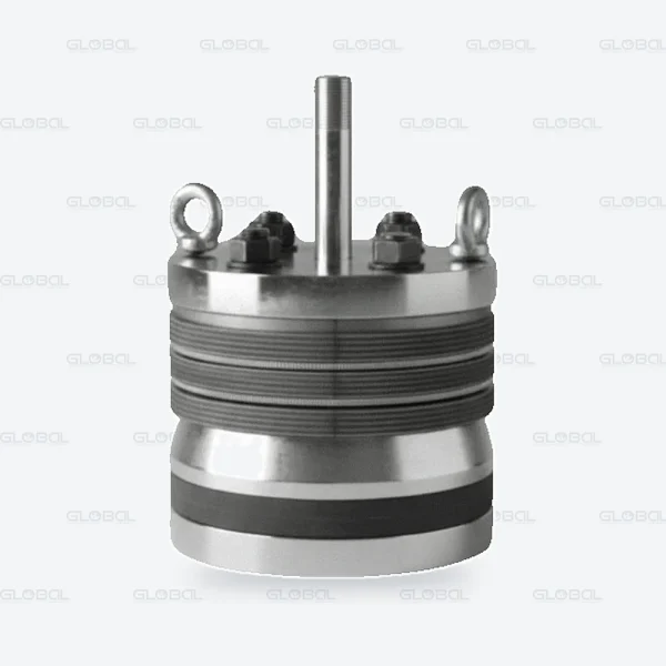 Featured
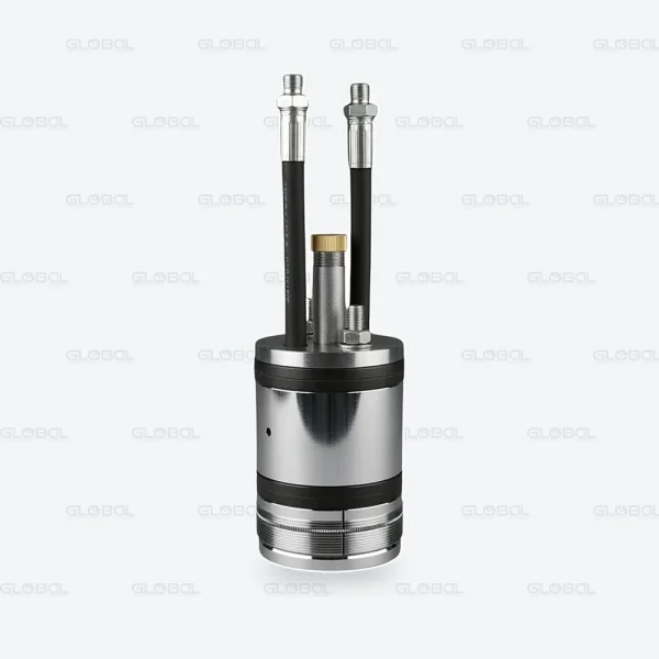
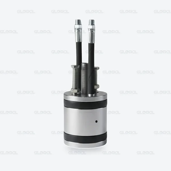
IN-MAX™ High-Pressure Inner Test Plug
View product →From a drawing or a worn sample to a finished rubber part, plus pressure testing on site or at our factory.
→Custom manufacturing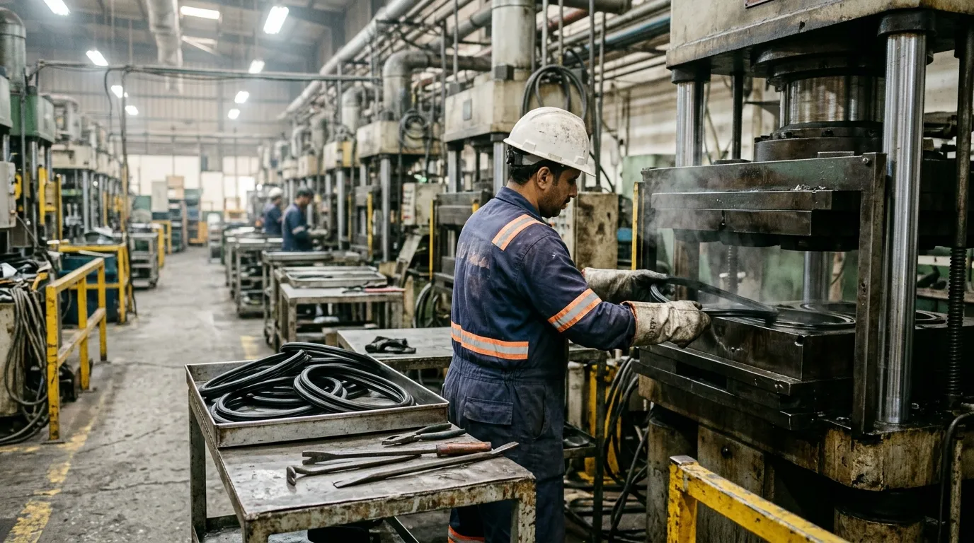
Get a compound proposal, a tooling quote and a lead time.
→Request a quoteFree engineering tools for pipe testing: pick a plug, size the test, and see it before you start.
→All toolsOne rubber factory, many worlds. Each industry has its own conditions and products.
→All industries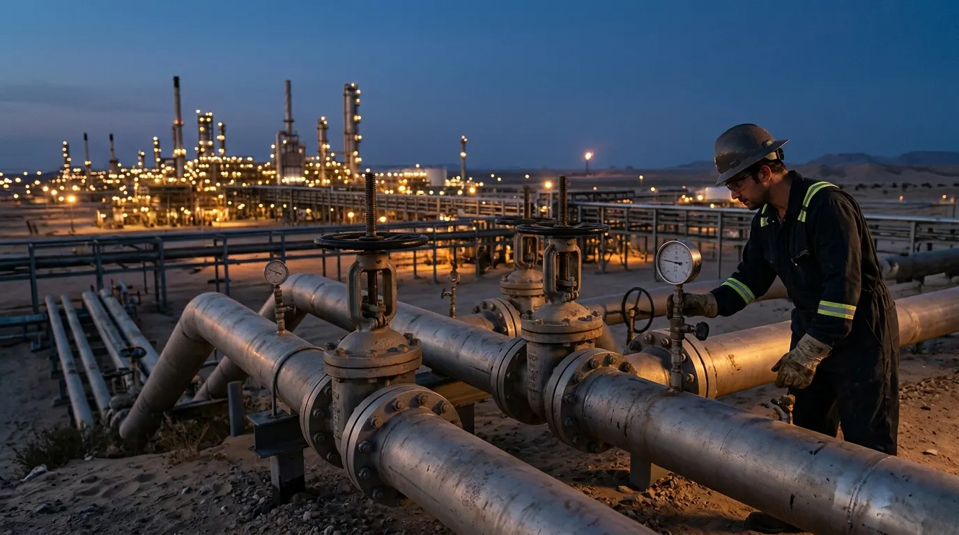 Oil & gasPipelines · Production
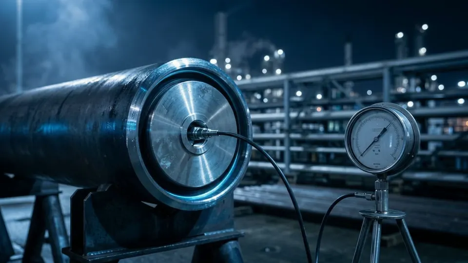 Petrochemical & refiningRefineries · Turnarounds
 Power & desalinationPower plants · Desalination
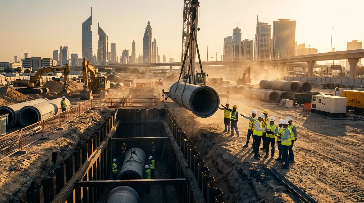 Water & pipelinesWater · Sewage
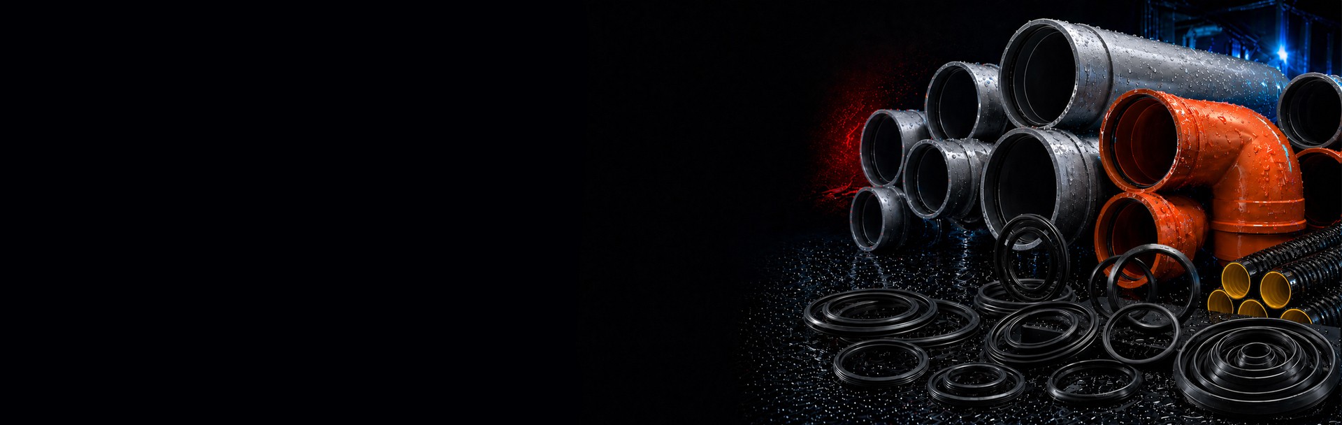 Pipe manufacturersPVC · HDPE · GRP pipes
 Military & defenseVehicles · Equipment
 Marine & portsPorts · Shipyards
 Civil worksInfrastructure
 General industriesFactories · Machine builders
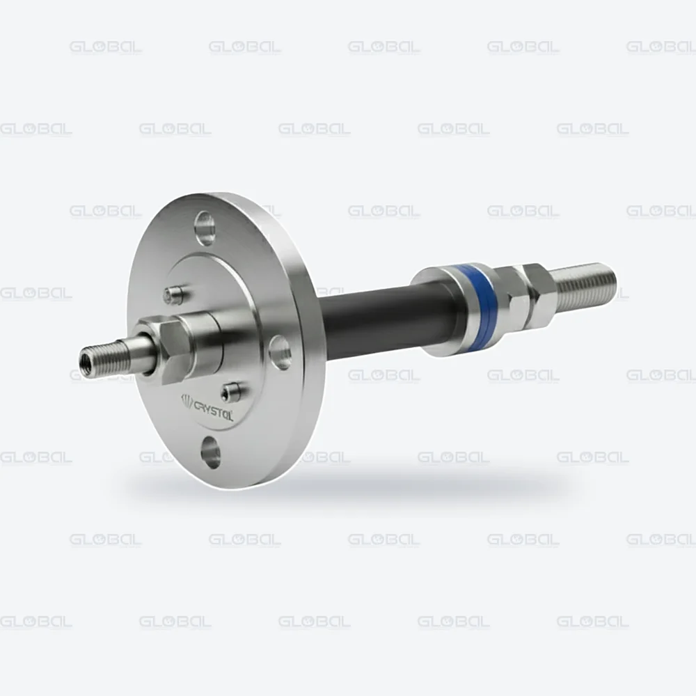
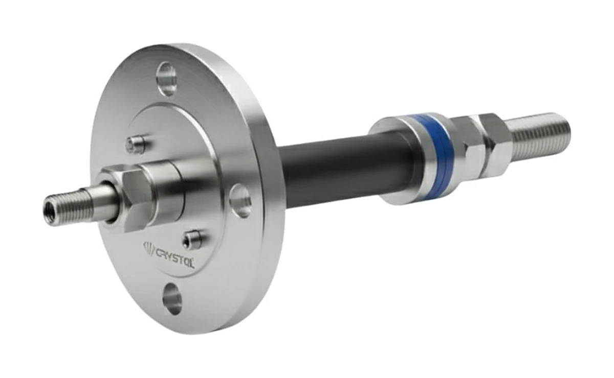
Mechanical plug for flange-to-pipe welding and testing. It bolts to the flange like a blind flange, seals inside the pipe beyond the weld and lets you purge, isolate, weld and test with one tool. Test pressure up to 2,250 psig (155 barg) by flange class; standard part numbers 6″ – 24″ (DN150 – DN600) in ANSI class 150, 300 and 600.
| Standard sizes | 6″ – 24″ (DN150 – DN600); 3/8″ – 48″ on request |
|---|---|
| Flange classes | ANSI 150, 300, 600 |
| Max. test pressure | 450 psig (31 barg) class 150; 1,125 psig (77.6 barg) class 300; 2,250 psig (155 barg) class 600 |
| Configuration | Weld plug / test plug |
| Purge | Inert gas through the ported centre shaft |
| Part numbers | 640001 – 640027 |
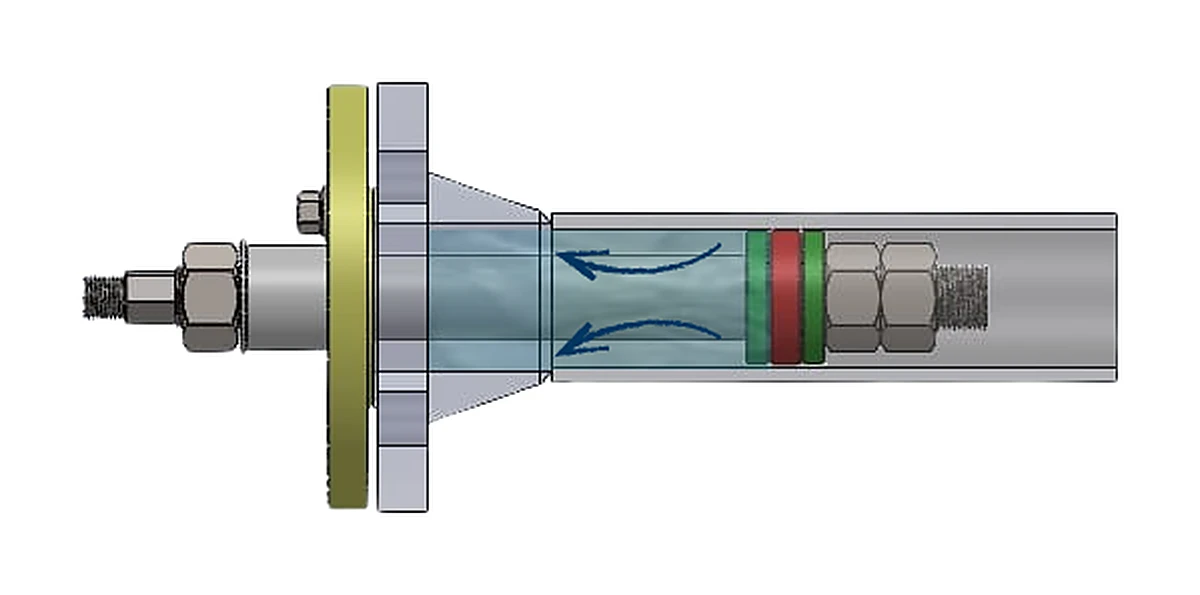
FLANGE-WELD™ is a mechanical plug for flange-to-pipe welding and hydrostatic testing. It bolts to the flange face with a gasket, like a blind flange, and its expanding seal locks inside the pipe beyond the weld. Only the small zone between the plate and the seal is filled and tested, so you never pressurise the whole line.
It works in two set-ups. As a weld plug, it isolates the line while you weld the flange to the pipe: the ported centre shaft lets you monitor upstream pressure and purge the weld area with inert gas. As a test plug, it hydrotests the finished weld, up to the maximum pressure for the flange class.
One tool covers purging, isolation, welding and testing, with very little water and no full-line pressurisation, which cuts test time on fabrication and maintenance work.
How to use
Sizes & part numbers
Choose your flange size and ANSI class: the matching part number, seal clearance, maximum test pressure, installation torque (normal – maximum) and hex nut wrench size are highlighted. Other sizes and ratings on request.
| P/N | Size | ANSI class | Seal clearance | Max. test pressure | Torque (normal – max.) | Hex nut wrench | |
|---|---|---|---|---|---|---|---|
| 6″ DN1503 classes | |||||||
| 640001 | 6″DN150 | 150 | 0.5″12.7 mm | 450 psi31 bar | 35–80 ft·lb47.5–108.5 N·m | 3/4″ | |
| 640002 | 6″DN150 | 300 | 0.5″12.7 mm | 1,125 psi77.6 bar | 45–80 ft·lb61.0–108.5 N·m | 3/4″ | |
| 640003 | 6″DN150 | 600 | 0.5″12.7 mm | 2,250 psi155 bar | 50–80 ft·lb67.8–108.5 N·m | 3/4″ | |
| 8″ DN2003 classes | |||||||
| 640004 | 8″DN200 | 150 | 0.5″12.7 mm | 450 psi31 bar | 60–155 ft·lb81.3–210.2 N·m | 1 1/16″ | |
| 640005 | 8″DN200 | 300 | 0.5″12.7 mm | 1,125 psi77.6 bar | 70–155 ft·lb94.9–210.2 N·m | 1 1/16″ | |
| 640006 | 8″DN200 | 600 | 0.5″12.7 mm | 2,250 psi155 bar | 80–155 ft·lb108.5–210.2 N·m | 1 1/16″ | |
| 10″ DN2503 classes | |||||||
| 640007 | 10″DN250 | 150 | 0.5″12.7 mm | 450 psi31 bar | 150–600 ft·lb203.4–813.5 N·m | 1 5/8″ | |
| 640008 | 10″DN250 | 300 | 0.5″12.7 mm | 1,125 psi77.6 bar | 200–600 ft·lb271.2–813.5 N·m | 1 5/8″ | |
| 640009 | 10″DN250 | 600 | 0.5″12.7 mm | 2,250 psi155 bar | 300–600 ft·lb406.8–813.5 N·m | 1 5/8″ | |
| 12″ DN3003 classes | |||||||
| 640010 | 12″DN300 | 150 | 0.5″12.7 mm | 450 psi31 bar | 150–600 ft·lb203.4–813.5 N·m | 1 5/8″ | |
| 640011 | 12″DN300 | 300 | 0.5″12.7 mm | 1,125 psi77.6 bar | 250–600 ft·lb339.0–813.5 N·m | 1 5/8″ | |
| 640012 | 12″DN300 | 600 | 0.5″12.7 mm | 2,250 psi155 bar | 300–600 ft·lb406.8–813.5 N·m | 1 5/8″ | |
| 14″ DN3503 classes | |||||||
| 640013 | 14″DN350 | 150 | 0.5″12.7 mm | 450 psi31 bar | 200–600 ft·lb271.2–813.5 N·m | 1 5/8″ | |
| 640014 | 14″DN350 | 300 | 0.5″12.7 mm | 1,125 psi77.6 bar | 300–600 ft·lb406.8–813.5 N·m | 1 5/8″ | |
| 640015 | 14″DN350 | 600 | 0.5″12.7 mm | 2,250 psi155 bar | 300–600 ft·lb406.8–813.5 N·m | 1 5/8″ | |
| 16″ DN4003 classes | |||||||
| 640016 | 16″DN400 | 150 | 0.5″12.7 mm | 450 psi31 bar | 200–600 ft·lb271.2–813.5 N·m | 1 5/8″ | |
| 640017 | 16″DN400 | 300 | 0.5″12.7 mm | 1,125 psi77.6 bar | 300–600 ft·lb406.8–813.5 N·m | 1 5/8″ | |
| 640018 | 16″DN400 | 600 | 0.5″12.7 mm | 2,250 psi155 bar | 300–600 ft·lb406.8–813.5 N·m | 1 5/8″ | |
| 18″ DN4503 classes | |||||||
| 640019 | 18″DN450 | 150 | 0.5″12.7 mm | 450 psi31 bar | 250–600 ft·lb339.0–813.5 N·m | 1 5/8″ | |
| 640020 | 18″DN450 | 300 | 0.5″12.7 mm | 1,125 psi77.6 bar | 350–600 ft·lb474.5–813.5 N·m | 1 5/8″ | |
| 640021 | 18″DN450 | 600 | 0.5″12.7 mm | 2,250 psi155 bar | 350–600 ft·lb474.5–813.5 N·m | 1 5/8″ | |
| 20″ DN5003 classes | |||||||
| 640022 | 20″DN500 | 150 | 0.5″12.7 mm | 450 psi31 bar | 250–600 ft·lb339.0–813.5 N·m | 1 5/8″ | |
| 640023 | 20″DN500 | 300 | 0.5″12.7 mm | 1,125 psi77.6 bar | 350–600 ft·lb474.5–813.5 N·m | 1 5/8″ | |
| 640024 | 20″DN500 | 600 | 0.5″12.7 mm | 2,250 psi155 bar | 350–600 ft·lb474.5–813.5 N·m | 1 5/8″ | |
| 24″ DN6003 classes | |||||||
| 640025 | 24″DN600 | 150 | 0.5″12.7 mm | 450 psi31 bar | 300–600 ft·lb406.8–813.5 N·m | 1 5/8″ | |
| 640026 | 24″DN600 | 300 | 0.5″12.7 mm | 1,125 psi77.6 bar | 400–600 ft·lb542.3–813.5 N·m | 1 5/8″ | |
| 640027 | 24″DN600 | 600 | 0.5″12.7 mm | 2,250 psi155 bar | 400–600 ft·lb542.3–813.5 N·m | 1 5/8″ | |
Never exceed the test pressure for the flange class, and never adjust the plug while it is under pressure. Use water and remove all air; keep everyone clear of the plug during the test. When welding, monitor the upstream pressure and stop at once if it rises; the pipe at the seal must never get too hot to touch. Do not let the weld protrude into the bore by more than the seal clearance, or the bore may need grinding before the plug comes out. Vent upstream vapours through about 50 ft (15 m) of hose, ending downwind of the weld.
Applications
Send us the pipe I.D., material and test pressure. We will confirm the right plug and lead time.
Product Enquiry
WhatsApp us